Disposable Vapes Are Free Batteries
5 million vapes were thrown away weekly in the UK. Each contains a rechargeable lithium cell. Here's what you could build with them.

5 million disposable vapes were thrown away every week in the UK. Each one contains a rechargeable lithium-ion cell rated for 500+ cycles. I used AI to plan what you could actually build with them. None of this has been tested yet -- it's a design exercise. If you build it first, let me know.
The Cell
Inside every Elf Bar, Lost Mary, and similar disposable vape sits a 13400 lithium-ion cell -- 13mm diameter, 40mm long, 3.7V nominal, ~550mAh. It's the same chemistry as your phone battery, rechargeable hundreds of times, and it was designed to be used once and thrown away.
Academic research confirms these cells retain 80-95% capacity after their brief vaping career. The best teardown guides come from Run Like Duck and Junglebiscuit. Extraction is straightforward: pop the end cap, pull the guts, cut wires one at a time (never both at once).
Ideas I Explored
AA Battery Adapter -- Dead End
A 13400 cell physically fits inside an AA shell. Add a buck converter to step 3.7V down to 1.5V and you've got a rechargeable AA. Companies like XTAR already sell this for $3-5 with USB-C charging. A DIY version costs ~$2.25, needs hard-to-source ICs (XM5232, LC9201D), and delivers worse capacity. Not worth it.
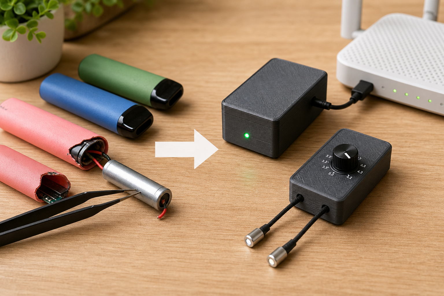
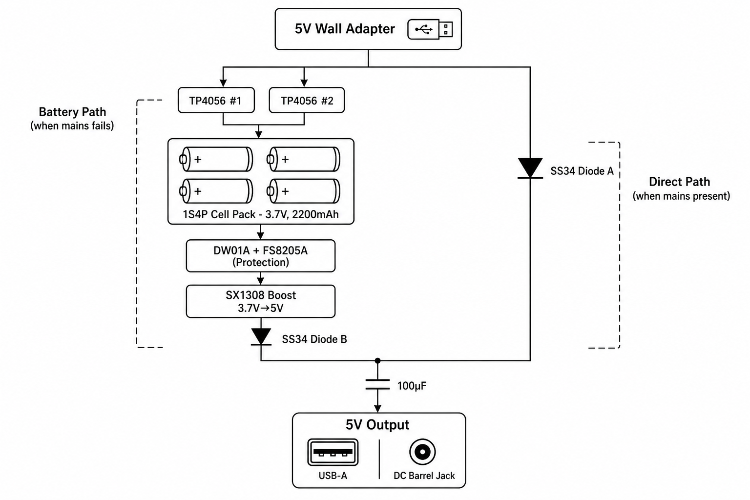
Mini UPS for Home Networking
Four cells in parallel (1S4P, 3.7V, ~2,200mAh) feeding a boost converter to 5V, with a Schottky diode OR'd power path for seamless mains failover. No microcontroller needed. Estimated ~$2.15 in parts, ~60 minutes of router backup. Commodity components (TP4056, SX1308, SS34 diodes). Others have built power banks from vape cells, but nobody's done a stationary UPS with automatic switchover.
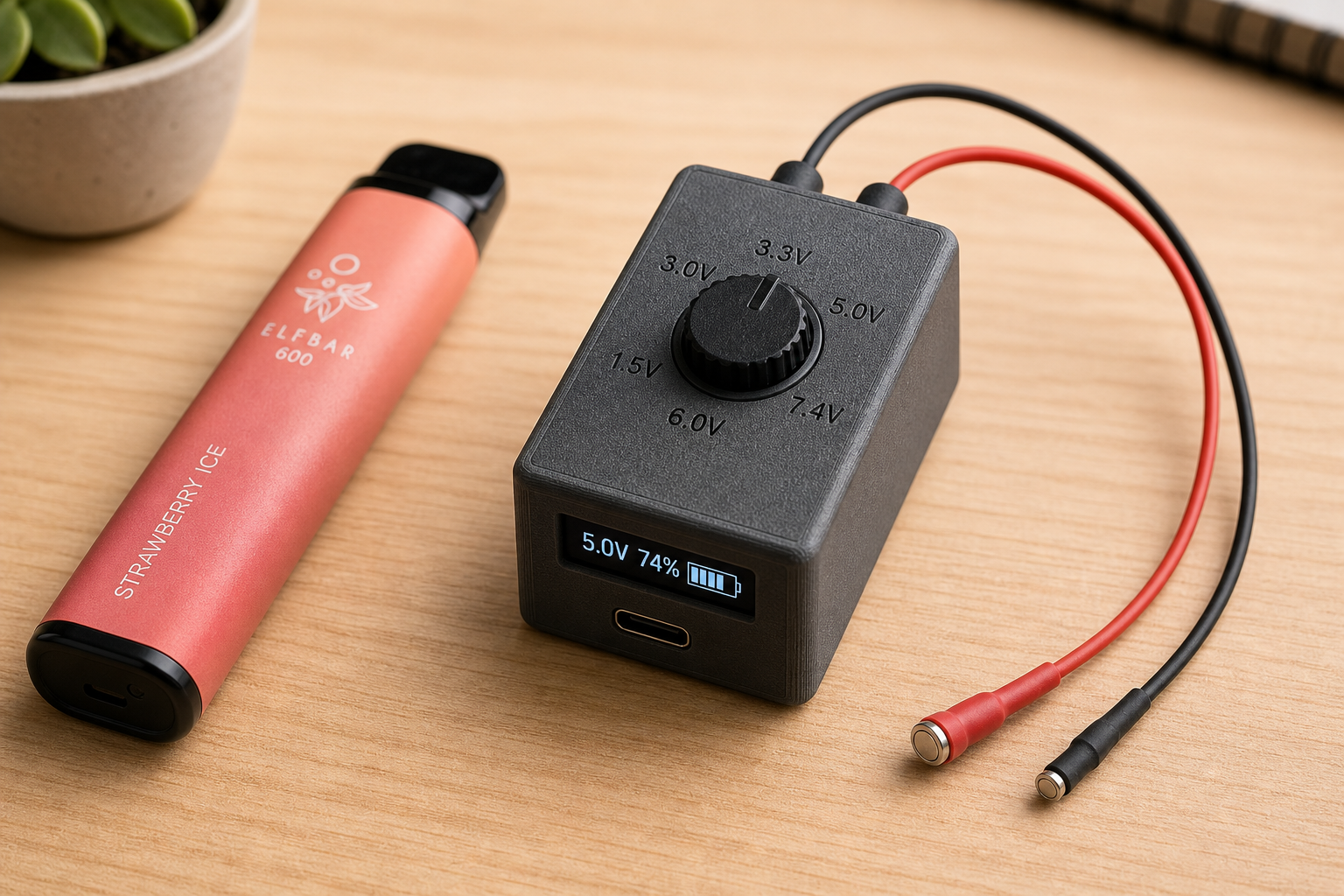
The Main Event: Magnetic Probe Pack
This is the idea I'm most interested in building. A pocket-sized, voltage-selectable power supply with magnetic-tipped probe cables, powered by four salvaged vape cells.
Why
You need a quick source of clean DC power. Your bench supply is at home. Your power bank outputs 5V USB only. You need 3.3V for an ESP32, or 6V for a motor, or 1.5V for a dead remote. Nothing pocket-sized exists with selectable voltage and probe outputs.
Architecture
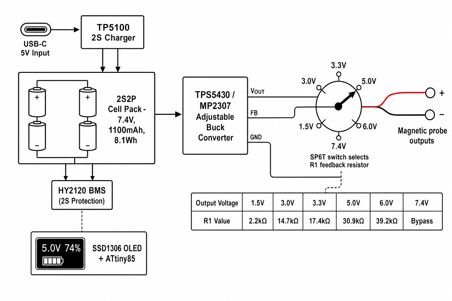
2S2P cell configuration -- two series pairs in parallel. 7.4V nominal, ~1,100mAh, ~8.1Wh. High enough to regulate down to any common voltage with good efficiency.
Adjustable buck converter (TPS5430 or MP2307) with a 6-position rotary switch that selects the feedback resistor to set output voltage:
| Output | R1 | R2 | Use case |
|---|---|---|---|
| 1.5V | 2.2kΩ | 10kΩ | AA replacement |
| 3.0V | 14.7kΩ | 10kΩ | 2× AA, coin cells |
| 3.3V | 17.4kΩ | 10kΩ | ESP32, STM32 |
| 5.0V | 30.9kΩ | 10kΩ | USB, Arduino, Pi |
| 6.0V | 39.2kΩ | 10kΩ | 4× AA, motors |
| 7.4V | -- | -- | Bypass (raw pack) |
R2 is fixed at 10kΩ. The switch connects one of five R1 values, or bypasses the regulator entirely. Standard 1% resistors, no trimming.
BMS: HY2120 (2S protection IC) with FS8205A dual MOSFETs. Mandatory for series cells -- handles over-charge, over-discharge, and short-circuit. Passive balancing via 100Ω bleeders + LEDs on each cell tap.
Charging: TP5100 module. Dedicated 2S charger, USB-C input, CC/CV profile, charges to 8.4V from 5V.
The Probes
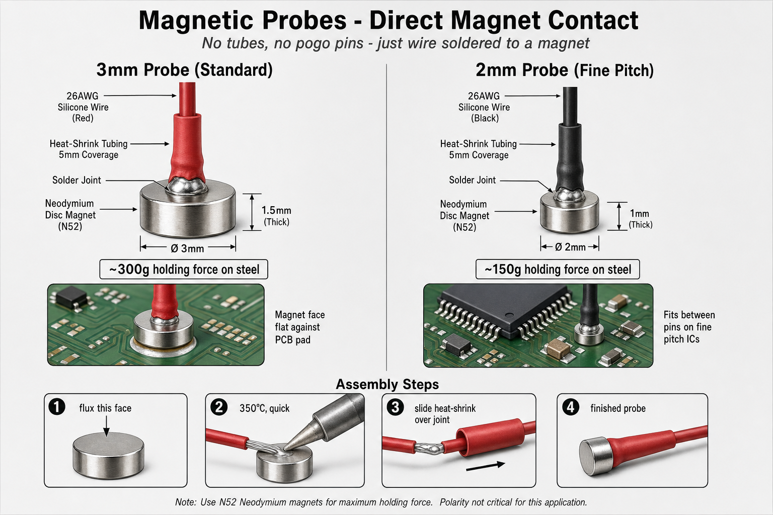
The simplest part. Solder a wire directly to a tiny neodymium disc magnet. Neodymium is electrically conductive (sintered metal alloy, not ceramic). The nickel plating takes solder with flux. The magnet is both the mechanical grip and the electrical contact.
Per probe: 3mm × 1.5mm N52 disc magnet + 500mm of 26AWG silicone wire + heat-shrink. Solder at 350°C, quick (don't demagnetise it). Two minutes, three cents.
Touch the magnet face to a PCB pad, battery terminal, or bare wire. On ferrous/tinned surfaces it grabs and holds (~300g on steel). Polarity coding: red heat-shrink + 3mm magnet (positive), black + 2mm magnet (negative) -- different sizes so you can tell them apart by touch.
Bill of Materials
| # | Component | Source | Cost |
|---|---|---|---|
| 1 | 13400 cells (×4, salvaged) | Disposable vapes | Free |
| 2 | HY2120 + FS8205A (2S BMS) | LCSC | ~$0.15 |
| 3 | TP5100 2S charger module | AliExpress | ~$0.50 |
| 4 | MP2307 buck module (adjustable) | AliExpress | ~$0.40 |
| 5 | SP6T rotary switch | AliExpress | ~$0.30 |
| 6 | Feedback resistors (5× 1%) | LCSC | ~$0.06 |
| 7 | Balancing resistors + LEDs | LCSC | ~$0.04 |
| 8 | SSD1306 OLED + ATtiny85 (optional) | AliExpress | ~$1.50 |
| 9 | N52 magnets (3mm + 2mm) + wire + heat-shrink | AliExpress | ~$0.15 |
| 10 | 3D printed enclosure + nickel strip | PETG filament | ~$0.60 |
| Total | ~$3.70 |
Enclosure
55mm × 35mm × 35mm PETG brick (lighter-sized). Rotary switch on top, OLED on one end, USB-C charge port on the bottom, magnet-tipped cables exiting through strain-relief grommets. Cells in a 2×2 array of 13mm wells. The optional OLED shows selected voltage and remaining capacity from a simple ATtiny85 voltage-to-percentage lookup.
Safety
- Test every cell before use: discard anything below 2.5V, above 250mΩ internal resistance, or that gets hot during charging.
- Never skip the BMS on series configurations. Unbalanced cells in series can cause thermal runaway.
- Match cells by measured capacity (within 10%) for multi-cell packs.
- Never charge salvaged cells unattended.
- Ventilate your enclosure. Don't seal it.
Links
- Chris Doel's Vape Power Bank -- 100W USB-C power bank from 35 vape cells
- RVBP Project -- IoT battery pack with ESP32 monitoring
- Run Like Duck -- early vape cell repurposing documentation
- Kentli PH5 Teardown -- commercial 1.5V Li-ion AA internals
- MDPI Batteries journal -- academic analysis of salvaged vape cells
This post was planned with AI assistance. The circuit designs, component selections, and resistor calculations are based on datasheet specifications but have not been physically built or tested. If you build one of these, I'd love to hear how it goes.